
| My Tormach PCNC-770 Hacks | |||
Figure 1
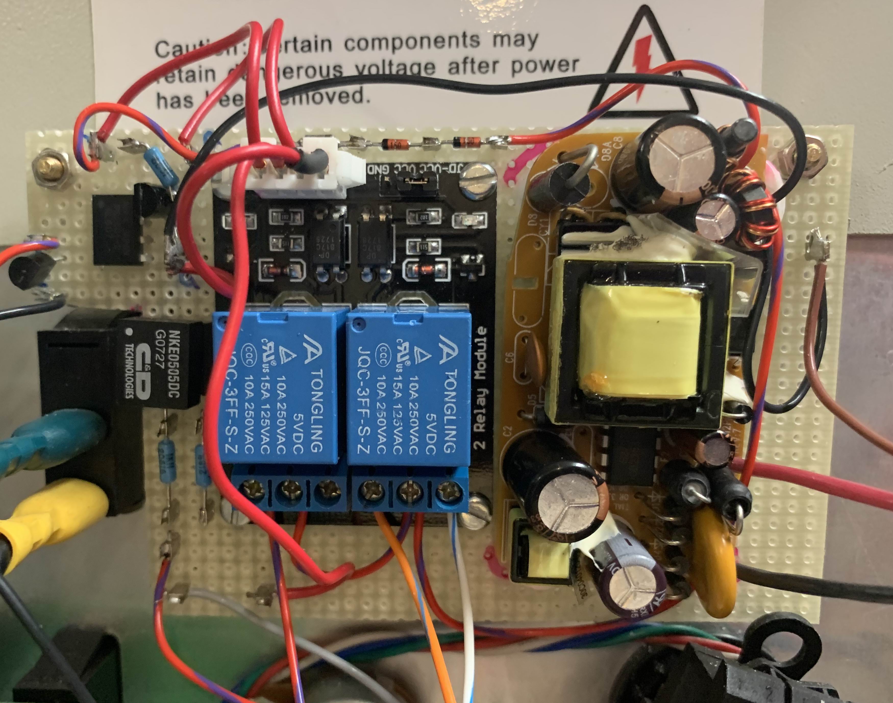 Figure 2
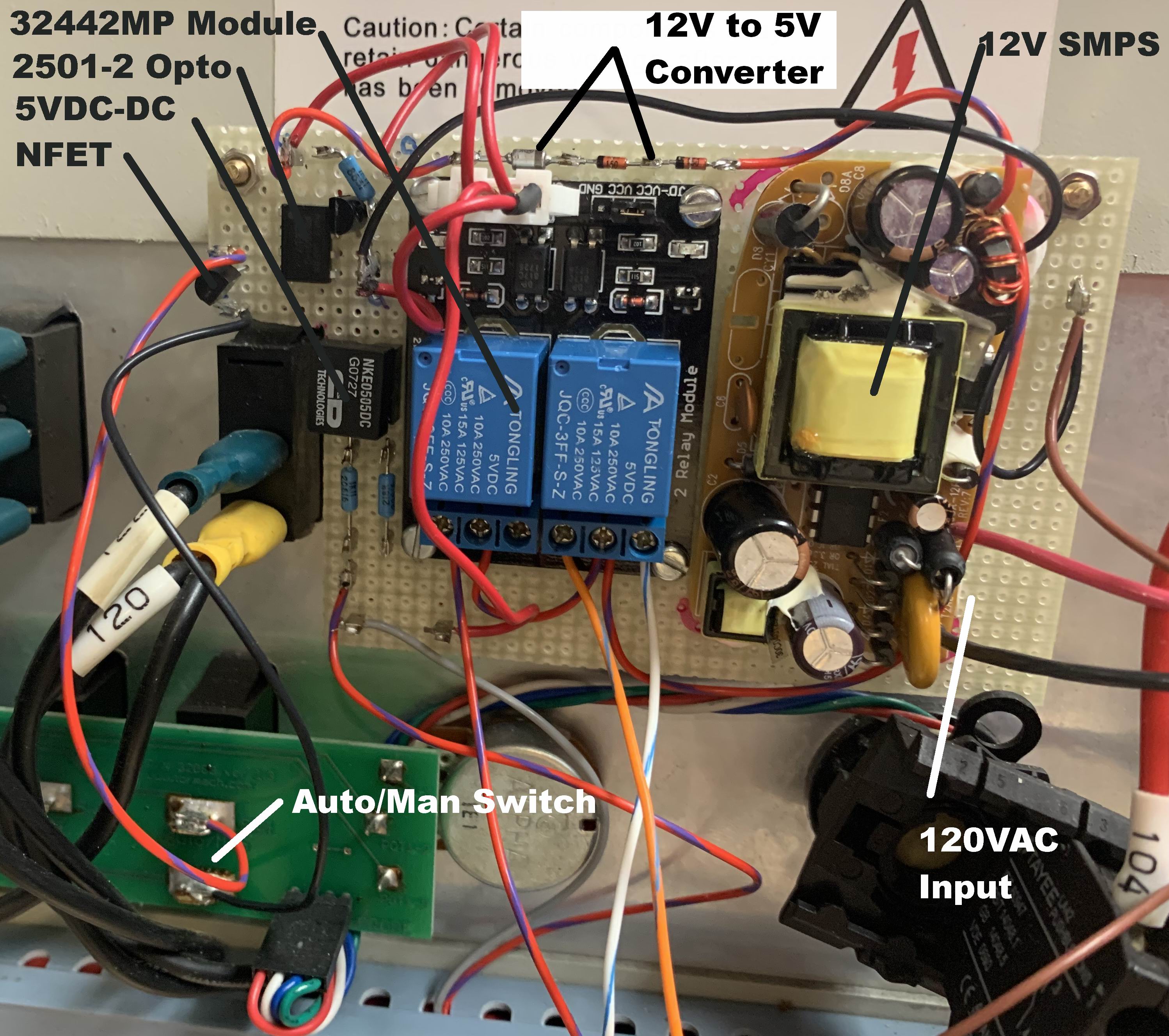 Figure 3
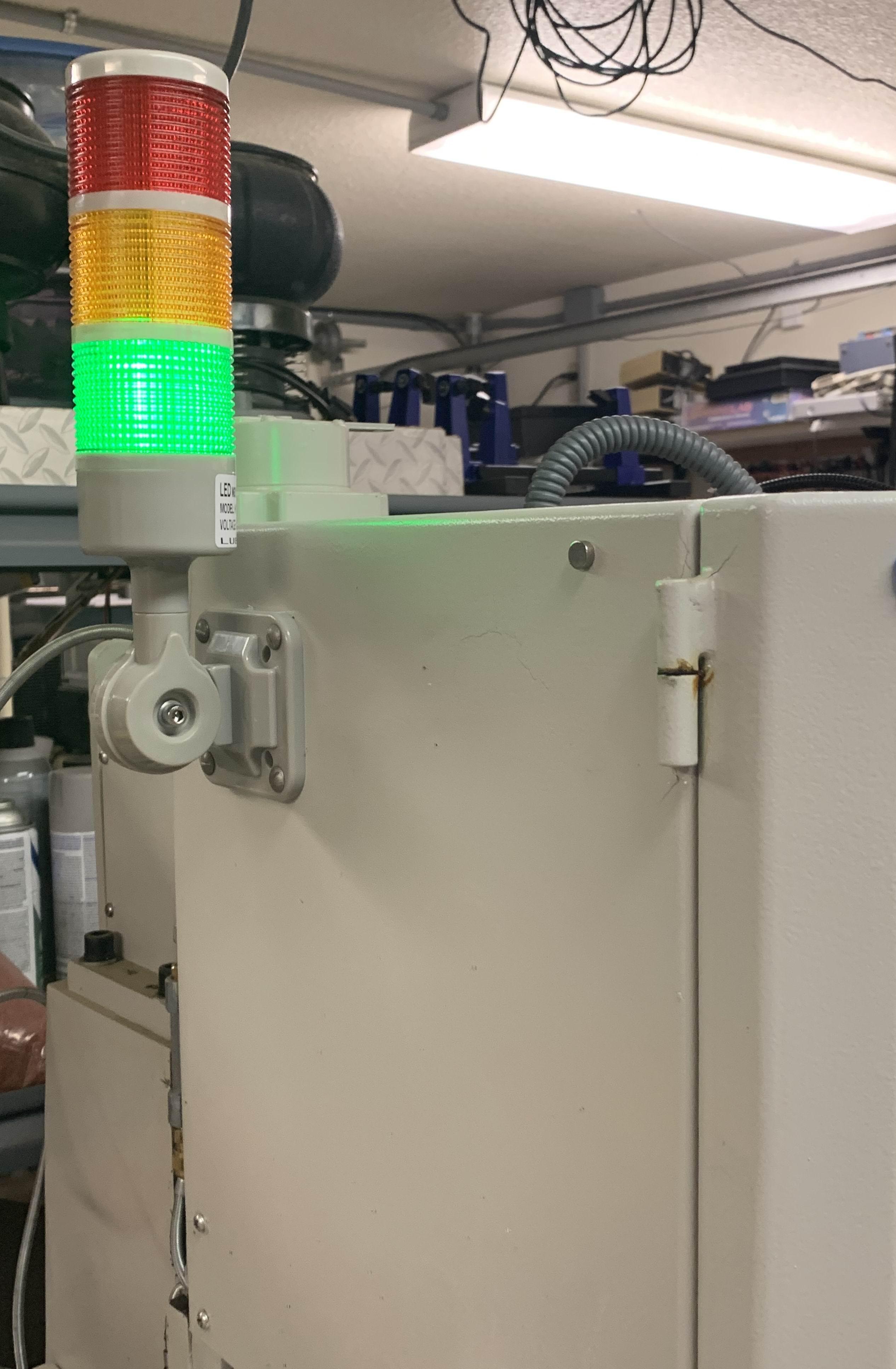 Figure 4
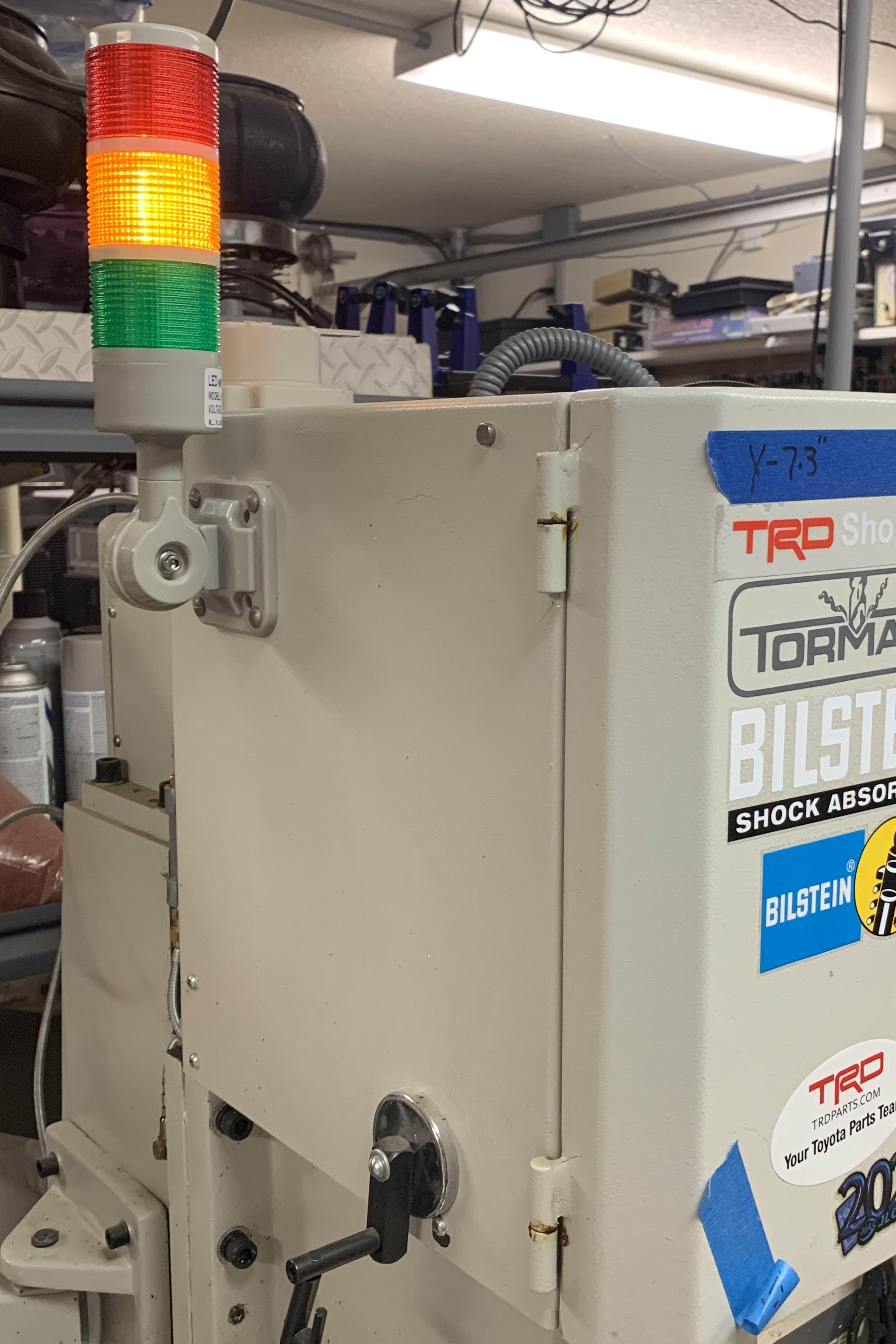 Figure 5
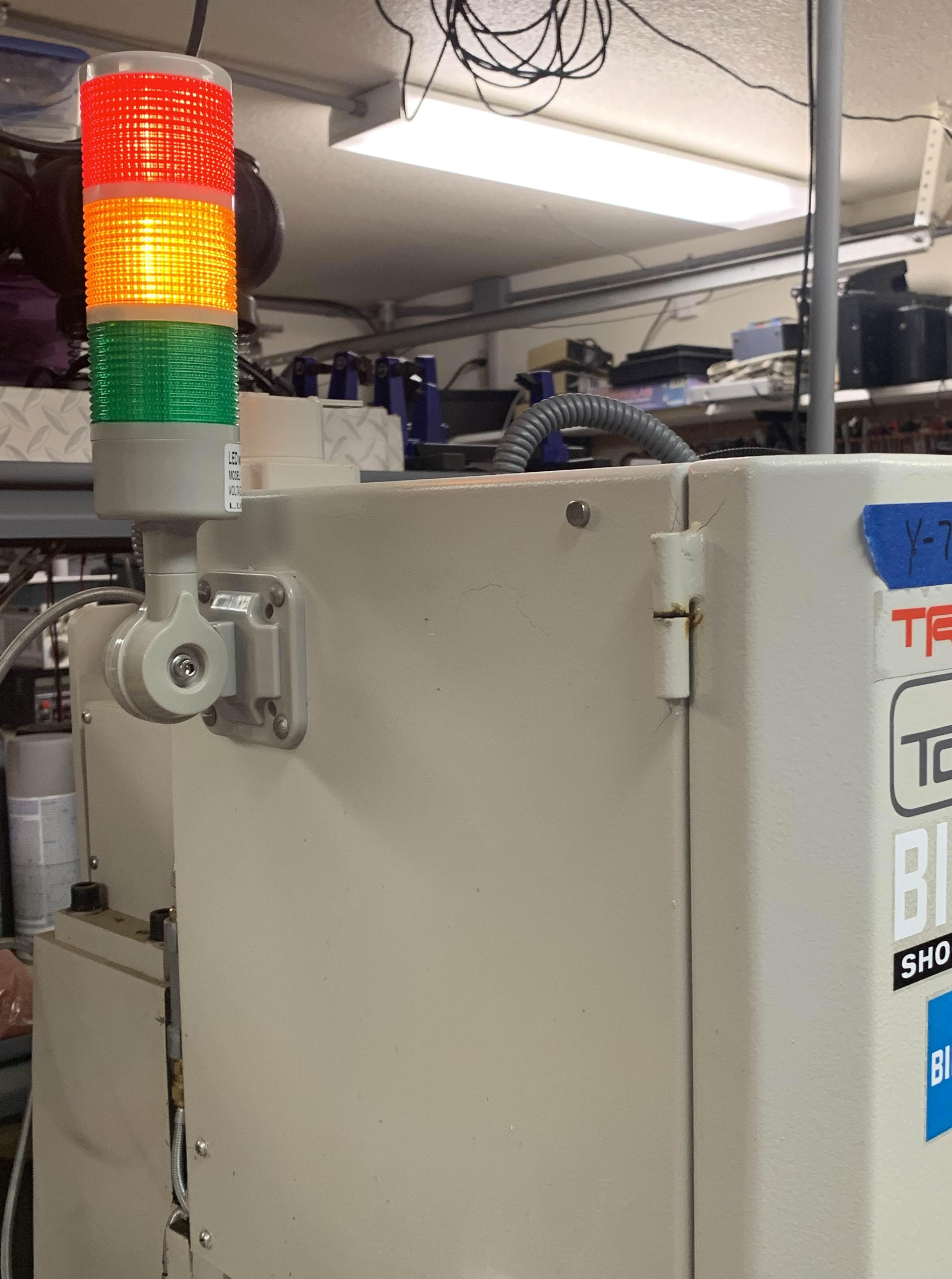 Figure 6
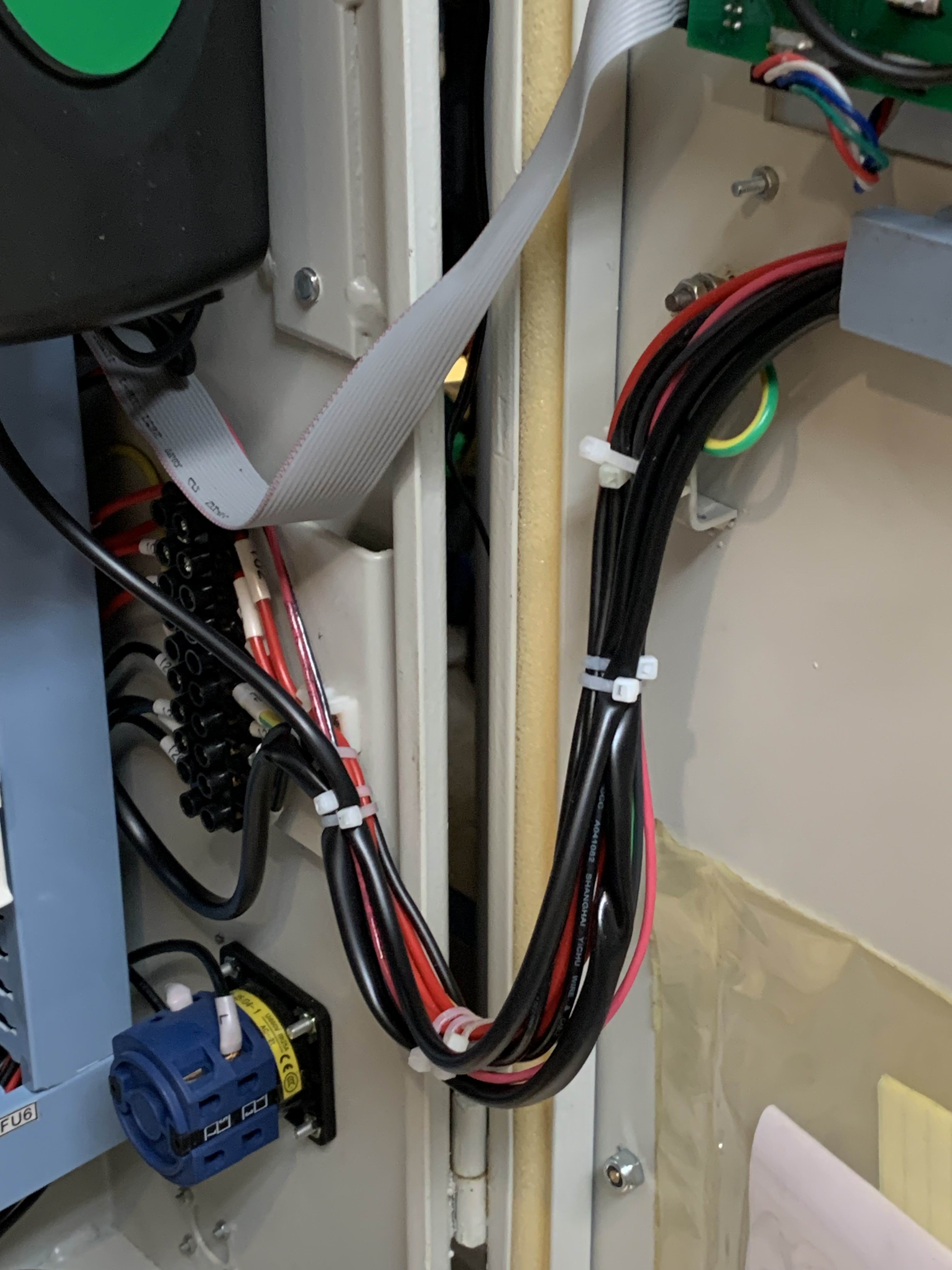 Figure 7
|
IntroI have owned a PCNC-770 Series 3 for about 9 years. In general, it has functioned very well and paid for itself in less than a year! But there are a few things that I wish Tormach had added to the control panel and computer interface. Because I often do manual machining for things like surfacing parts or when edge finding, I an constantly switching between Auto and Manual. It is very easy to return to the computer to run a machining program while the switch is still in Manual. The program will surely start and move the tool into position without the spindle starting! This is exacerbated by the chosen location of the monitor arm and keyboard on the left of the machine. (Being left-handed, placed on the right would be quite awkward.) Working in this position, the main control panel is visually blocked by the motor column. Depending on the current tool heigth, the tool may reach the work before the brain recognizes the error and I can click on stop or reach aroung for the ESTOP! I don't use a lot of large cutters in automatic mode, but have broken a number of 1/16" mills this way. I would have liked to see the following features implemented:
The PlanMy current resolution to this problem was to install a warning light column on the left-hand side of the motor column box. I would use the GREEN indicator to indicate AUTO mode and the YELLOW indicator to show the switch was in MANUAL. But the only signal available from the controller panel was the actual AUTO/MANUAL switch. On investigating, I found that the switch had ~12VDC across it in AUTO mode. (Of course in MANUAL it is a short!) Further, the switch interfaces directly with the main Tormach hardware controller and there is no detailed information regarding the internals of this PCB. The best I could determine was that the source impedance of the 12VDC signal was about 1000 ohms. This was much too high to use as a control directly as any current drawn would quickly disturb the 12V signal at the controller in AUTO mode. (I found that dropping the voltage to about 9VDC was enough to confuse the controller about the mode it was in.) I could have replaced the switch with a 2-pole unit to get a spare contact, but that would have altered the panel look and I wanted to work with as much stuff that was on hand as possible. So the plan was to:
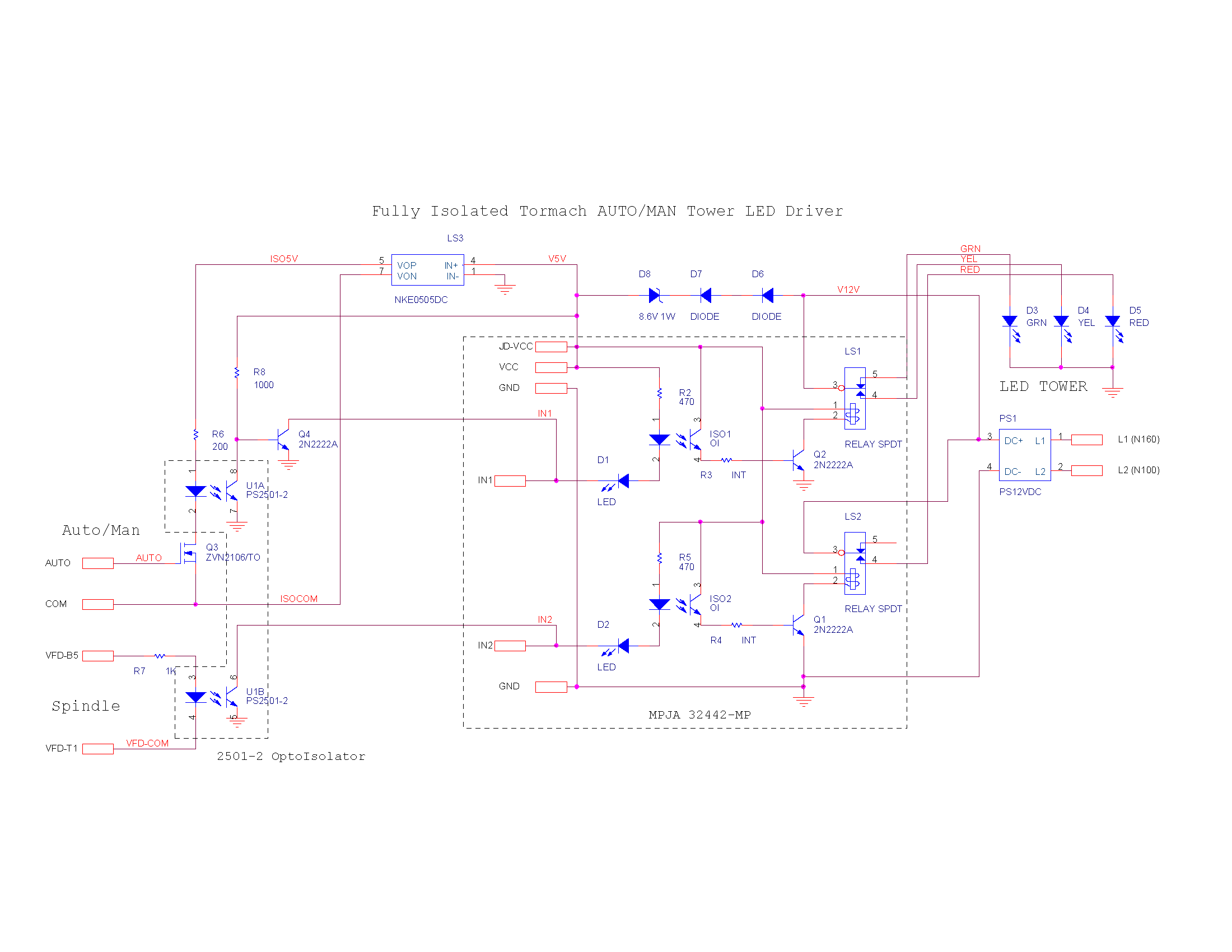
I did not want the relays energized in "Auto" or "spindle off" mode (most common state). But that meant that the logic state of the isolators in the relay module were the wrong direction. Since I had to isolate and buffer the Auto/Manual switch any way, I added a separate 2501-2 optoisolator that would also invert the logic levels. In order to power the Auto/Manual switch buffer I added a tiny 5VDC-5VDC isolation supply I had that came in an 8-pin DIP form. The ImplementationFigure 1 & 2 show how I attached the PCBs to a scrap of perf-board that was fastened to the existing front panel mounting screws. (You can click on any photo for an enlargement.) I taped the 120VAC power for the SMPS from Tormach nodes N160 (Line) and N100 (neutral) such that when in E-Stop mode all power was still removed from the inside of the front panel. This was an essential safety precaution. Figures 3, 4 & 5 show how I mounted the LED column on the left upper back of the spindle motor box for good visibility. The power wiring was routed through the existing spindle motor conduit and into the wiring loom in the back of the controller. From there all of the wires needed for the column are tie-wrapped to the door wiring loop (Figure 6) and routed into the door wiring loom. The complete control schematic is shown in Figure 7. |
||
